
Opposing Currents
September 20, 2022 | By John Siegenthaler
When it comes to designing systems with heat exchangers, stick with counterflow piping.
Heat exchangers, in all their varied types and sizes, allow heat to move from one fluid to another without any contact between those fluids. They add considerable versatility to hydronic system design. Common applications include domestic water heating, snow melting and hydronic subsystems for garage floor heating.
Flat plate heat exchangers have captured much of the market. More specifically, “brazed plate” stainless steel flat plate heat exchangers (BPHX) are now available from several suppliers in a wide range of sizes. They are ideally suited for residential and light commercial applications.
This type of heat exchanger is made by assembling a stack of pre-formed stainless steel plates that have copper bonded to them around their perimeter, and at points of contact between adjacent plates. The concept is shown in Figure 1.
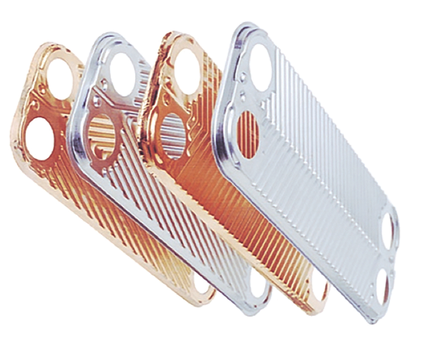
Figure 1. Example of typical brazed plate stainless steel flat plate heat exchanger (BPHX) assembly.
The stack is then compressed and heated in an oven to approximately 2,000F to braze the surfaces and perimeters together.
Most manufacturers of brazed plate heat exchangers have standardized plates sizes. Typical plate dimensions are 3 x 8 in., 5 x 12 in., and 10 x 20 in. For a given plate size, heat exchange ratings are increased by adding plates to the “stack” that become the overall heat exchanger.
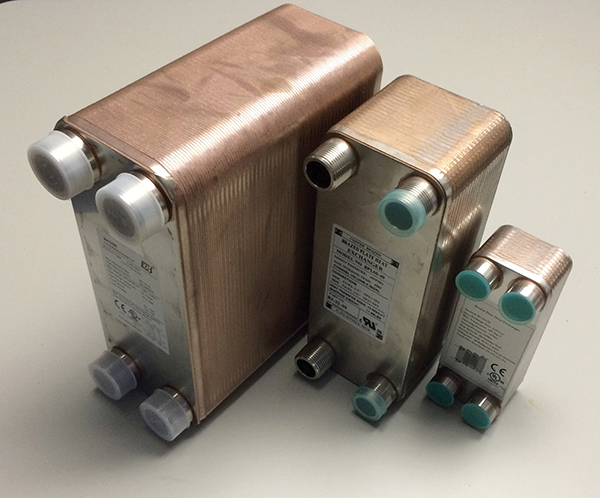
Brazed plate heat exchangers are commonly described by the nominal size of their plates and the number of plates in the stack. For example, a 5 x 12 x 40 brazed plate heat exchanger has 40 plates, of nominal dimension 5 x 12 in. One unique plate forms the back of the heat exchanger (e.g, it has no holes through it). Another unique plate forms the front of the heat exchanger, and transitions to the four piping connections. Figure 2 shows examples of brazed plate stainless steel heat exchangers ranging from a 5 x 12 x 100 plate unit, to a relatively small 3 x 8 x 10 plate unit.
Flow direction matters
Assuming the channels between the plates were numbered, one fluid passes from one end of the heat exchanger to the other through the odd numbered channels (1,3,5,6, etc.). The other fluid passes from one end of the heat exchanger to the other through the even numbered channels (2,4,6,8, etc.).
There are two possible ways to pipe up a flat plate heat exchanger. The two entering fluids streams could be moving in the same direction, or in opposite directions. When the two streams flow in the same direction the configuration is called “parallel flow.” When the two streams flow in opposite directions the configuration is called “counterflow.” These two flow configurations, along with representative temperature changes of both fluid streams, are shown in Figure 3.
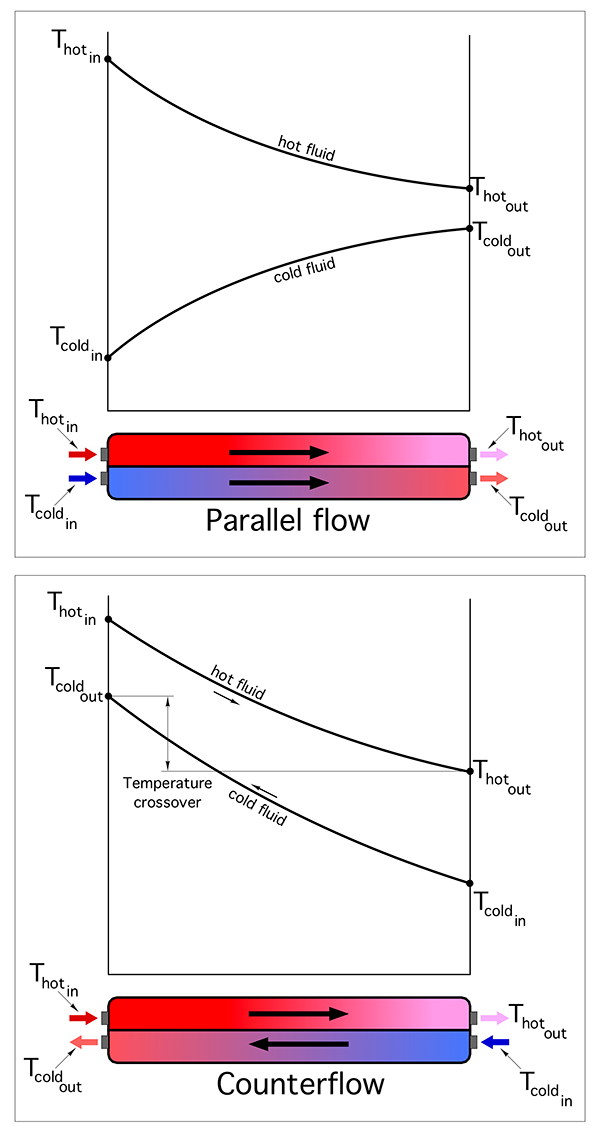
Figure 3. There are two ways to pipe up a flat plate heat exchanger: parallel flow or counterflow.
You can see that the temperature difference between the hot fluid and cool fluid changes considerably depending on where it is measured within the heat exchanger. For the parallel flow heat exchanger the temperature difference at the left side, where both fluids enter, is very large. But this difference decreases rapidly as the fluids exchange heat and move toward the outlet ports. There’s also a variation in the temperature difference between the fluids as they move through the counterflow heat exchanger.
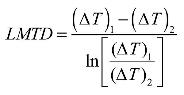
The rate of heat transfer depends on how the temperature differences at all locations along the fluid pathways “average out.” Heat transfer theory can be used to prove that this average temperature difference, which is more specifically called the “log mean temperature difference” (abbreviated at LMTD), can be calculated using Formula 1.
Formula 1:
Where:
LMDT = log mean temperature difference (F)
(∆T)1 = temperature difference between the two fluids at one end of the heat exchanger (F)
(∆T)2 = temperature difference between the two fluids at the other end of the heat exchanger (F)
ln [ ] = the natural logarithm of the quantity in the square brackets.
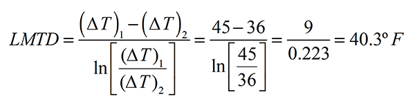
Here’s an example of how to use Formula 1: Calculate the LMTD of the heat exchanger shown in Figure 4.
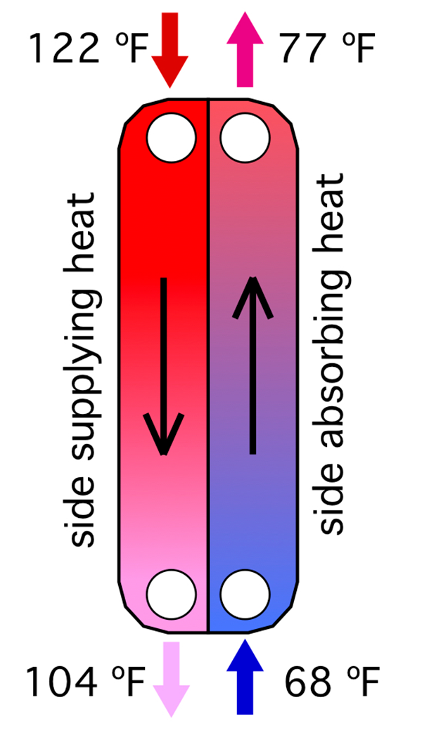
Just carefully put the numbers into the formula. Let (∆T)1 be assigned to the top end of the heat exchanger. Thus (∆T)1 = 122-77 = 45F. This means that (∆T)2 is at bottom end of the heat exchanger. Thus (∆T)2 = 104-68 = 36F. Putting these values into Formula 1 yields:
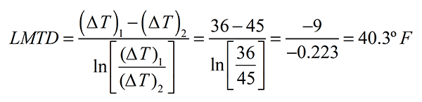
Reversing the ends of the heat exchanger representing (∆T)1 and (∆T)2 would make (∆T)1 = 36F, and (∆T)2 = 45F. Putting these values into formula 1 yields the same result.
Maximizing LMTD
The higher LMTD at which any heat exchanger operates, the greater the rate of heat transfer, all other conditions being equal.
Heat transfer theory can also be used to prove a very important concept in the application of heat exchangers:
The LMTD of a heat exchanger configured for counterflow will always be higher than that of the same heat exchanger configured for parallel flow, and having the same entering and exiting conditions for both flow streams.
This implies that heat exchangers should always be configured for counterflow when the goal is to maximize the rate of heat transfer.
Figure 5 shows a piping schematic where the heat exchanger is configured for counterflow.
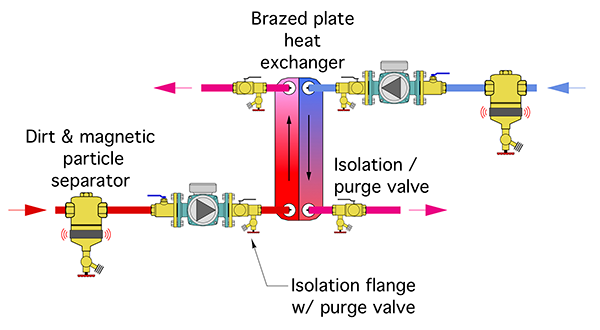
Figure 5. Piping schematic configured for counterflow.
Always check your piping schematics, or schematics that you may be approving for others to use, to be sure that all heat exchangers are piped for counterflow.
Check any installations that you are inspecting, that include heat exchangers, to be sure that they are operating in counterflow.
Let software do the hard work
Although it’s possible to manually estimate heat exchanger performance, the calculations are complex and time consuming. Modern practitioners use one of several available heat exchanger software tools available from manufacturers to rapidly evaluate “what if” scenarios, which lead to a final model selection.
In most cases a brazed plate heat exchanger will be sized to pass a given rate of heat transfer when the difference between the entering hot fluid temperature and the leaving cooling fluid temperature is no more than 5F.
Here are a few final application points regarding heat exchangers:
“Cleanliness is next to godliness” when it comes to heat exchanger performance. It’s always a good idea to put a high efficiency dirt separator, preferably one with a magnet, up stream of both inlet ports of any heat exchanger. You can see these in Figure 5, along with isolation and purging valves. The latter can be used, if ever necessary, the isolate each side of the heat exchanger and chemically clean scaling from internal surfaces.
Always support heat exchangers to reduce stress on the connecting piping. Several types of brackets are available and they range from a simple steel “shelf” bracket, to brackets that bolt directly to the threaded studs supplied on some heat exchangers.
Finally, if the heat exchanger will be operating with chilled fluids, which are lower than the interior dewpoint temperature, be sure it’s fully wrapped with elastomeric foam insulation or other vapour impermeable insulation material.
Stick with counterflow piping and the details mentioned above, and then stand back and be amazed at the incredible performance of modern brazed plate heat exchangers. <>

John Siegenthaler

